Point-based Rendering
Normal Detection
The initial datasets are quite basic, each point has a color and a position. This helps reduce the amount of data which can become staggeringly large when dealing with hundreds of millions of points. Still, normals are usually desired for each point so that splatting or lighting calculations can be performed.
We use pcl -- the pointcloud library -- to estimate normals for our point clouds. If I understood correctly, it works by estimating a best plane fit for a small subsection of the clouds. Even with OpenMP enabled it is quite time-consuming and we are using a preprocessing step to do so.
Splatting
The problem with points is that they do not have a physical extend. In OpenGL the rasterised point size can be specified to simulate 'fat' points. However this leads to problems as the z-test is only performed at the original vertex -- the center of the pixel. Overlapping 'fat' pixels are therefore not supported.
One idea is using 'splatting' instead of rendering points directly. Each point is assumed to be a small patch -- a splat (usually a circle). Initially, the projection of the splats were calculated and the resulting ellipsis drawn onto the framebuffer. However with modern cards it is possible to create the splats in the geometry shader. This creates correctly distorted splats while still requiring only the transfer of point data.
Calculating Splat Radii
An initial estimation of the splat radius is done during normal calculation. For each point a K-nearest neighbour (KNN) test is performed to find the 8-10 closest points. The average distance to these neighbour points is the splat radius (which can also be changed during runtime).
Drawing Splats
The splats are drawn by submitting a lot of vertices to be drawn as points.
Vertex Shader
The vertex shader is just a passthrough shader -- in fact, it does not even transform the vertex as this will be done for the complete extracted splat in the geometry shader.
#version 330

// The vertex data. The normal stores the normal and the
// calculated radius of the splat.
layout(location = 0) in vec3 vertexPosition;
layout(location = 1) in vec3 vertexColor;
layout(location = 2) in vec4 vertexNormal;

out VertexData
{
    vec3  color;
  vec3  normal;
  float radius;
} vertexOut;

void main()
{
  gl_Position = vec4(vertexPosition, 1.0);

  vertexOut.color = vertexColor;
  vertexOut.normal = vertexNormal.xyz;
  vertexOut.radius = vertexNormal.w;
}
Geometry Shader
The geometry shader is the actual work horse here. It calculates the normal and position of the splat in world coordinates and the four vertices. The vertices are aligned to the splat's tangent space which can be calculated from the normal and a helper vector (similar to the idea of the up vector in lookAt functions). Because this calculation can become unstable if the angle gets too small, there are two helper vectors and, depending on the normal's primary axis one is chosen.
Once tangent space has been calculated the four corner vertices are created from fixed offsets in tangent space. This offset is primarily the radius of the splat but a user should be able to (globally) influence this as well. After the offset is added the final vertex position is calculated by multiplying it with the modelview-projection matrix and is emitted.
A small addition to the code is that it omits all points whose splat radius is 0. The removes outliers in the data set (those without close neighbours) and does not draw them.
#version 150

// we accept points and render quads
layout (points) in;
layout (triangle_strip, max_vertices=4) out;

uniform mat4 modelMatrix = mat4(1.0);
uniform mat4 viewMatrix;
uniform mat4 projectionMatrix;

// This uniform allows to manually change the splat size
uniform float splatSize = 1.0;

in VertexData
{
  vec3  color;
  vec3  normal;
  float radius;
} VertexIn[];

out FragmentData
{
  vec2 texcoord;
  vec3 color;
} VertexOut;

void main()
{
  // discard outliers
  if (VertexIn[0].radius > 0.0)
  {

    // Matrix setup
    mat4 mvp = projectionMatrix * viewMatrix * modelMatrix;
    mat3 normalMatrix = inverse(transpose(mat3(modelMatrix[0].xyz, modelMatrix[1].xyz, modelMatrix[2].xyz)));

    vec4 pointCenter = gl_in[0].gl_Position;
    vec3 pointNormal = normalize(normalMatrix * VertexIn[0].normal);

    // create tangent space. Helper vectors dependent on major orientation of normal
    vec3 u, v;
    if (abs(pointNormal.y) > abs(pointNormal.x))
    {
      v = cross(pointNormal, vec3(1.0, 0.0, 0.0));
      u = cross(pointNormal, v);
    }
    else
    {
      v = cross(vec3(0.0, 1.0, 0.0), pointNormal);
      u = cross(pointNormal, v);
    }

    // Scale the splat
    u *= VertexIn[0].radius;
    v *= VertexIn[0].radius;

    // Manually alter size
    u *= (splatSize / 2.0);
    v *= (splatSize / 2.0);

    // Calculate the four corner vertices of the quad
    vec4 a = pointCenter + vec4(-u-v, 0.0);
    vec4 b = pointCenter + vec4(-u+v, 0.0);
    vec4 c = pointCenter + vec4(+u+v, 0.0);
    vec4 d = pointCenter + vec4(+u-v, 0.0);

    // transform the four points. Note the order of output
    gl_Position = mvp * b;
    VertexOut.texcoord = vec2(-1.0, 1.0);
    VertexOut.color = VertexIn[0].color;
    EmitVertex();

    gl_Position = mvp * a;
    VertexOut.texcoord = vec2(-1.0, -1.0);
    EmitVertex();

    gl_Position = mvp * c;
    VertexOut.texcoord = vec2(1.0, 1.0);
    EmitVertex();

    gl_Position = mvp * d;
    VertexOut.texcoord = vec2(1.0, -1.0);
    EmitVertex();

  }

}
Fragment Shader
The fragment shader's job is primarily drawing the splat on screen. To make it look closer to an actual splat (and therefore more liek a point sample), a disk is drawn. This is usually performed by enabling alpha blending and drawing a transparent disk but alpha blending slows down rendering (due to the framebuffer readback etc).
In this case, the texture coordinates of the splat are converted to radial coordinates which are used as inputs to determine whether a fragment is part of the circle or not.
#version 330

in FragmentData
{
  vec2 texcoord;
  vec3 color;
} FragmentIn;

out vec4 fragmentColor;

void main()
{

  // calculate whether this fragment is inside or outside the splat circle
  // tex coords from -1.0 to 1.0
  if ((pow(FragmentIn.texcoord, 2.0) + pow( FragmentIn.texcoord, 2.0) > 1.0)
    discard;

  fragmentColor = vec4(FragmentIn.color, 1.0);

}
-
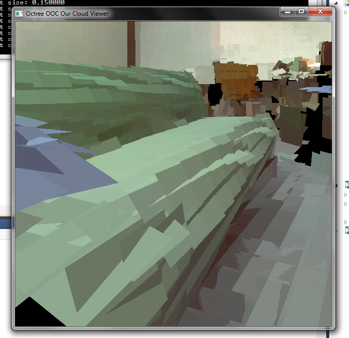
Large splats
The initial implementation of splatting. Large quads are calculated in the geometry shader and drawn. The overlapping areas don't look very nice. -
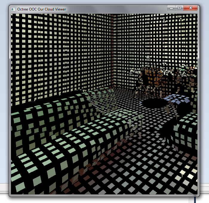
Splatting
The user is able to further change the splat radius during runtime. Also note the black 'shadow' behind the couch. This area was hidden from the scanner during scanning and therefore contains no point data. -
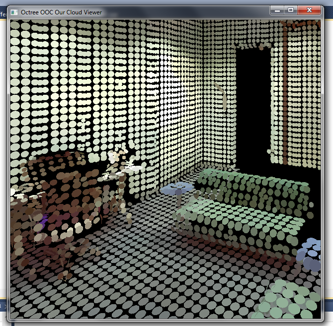
Round splats
Finally, the fragment shader can evaluate the fragment position and compared to the circle equation and easily create round splats. These are conceptually also closer to point samples than square splats are.
Mirror Rendering in Point Datasets
LiDAR scanners have one big problem: they do not detect mirrors. The distance detection is LASER based and the LASER gets reflected by the mirror. Everything the mirror 'sees' gets inserted -- mirrored -- into the other point cloud. These points have to be deleted manually during reconstruction, leaving a hole in the data set.
So, the idea is that while you are already busy deleting these points, you can mark up the mirror plane and its extend in the point cloud. During rendering, this plane has one extra rendering pass and renders the point cloud into an FBO. Finally, we can use projective texturing to display the content correctly.
It works fairly well and the math is non-intrusive enough that only the viewmatrix needs changing when rendering into the mirror, but the biggest problem is currently the performance drop due to the extra render pass.
-
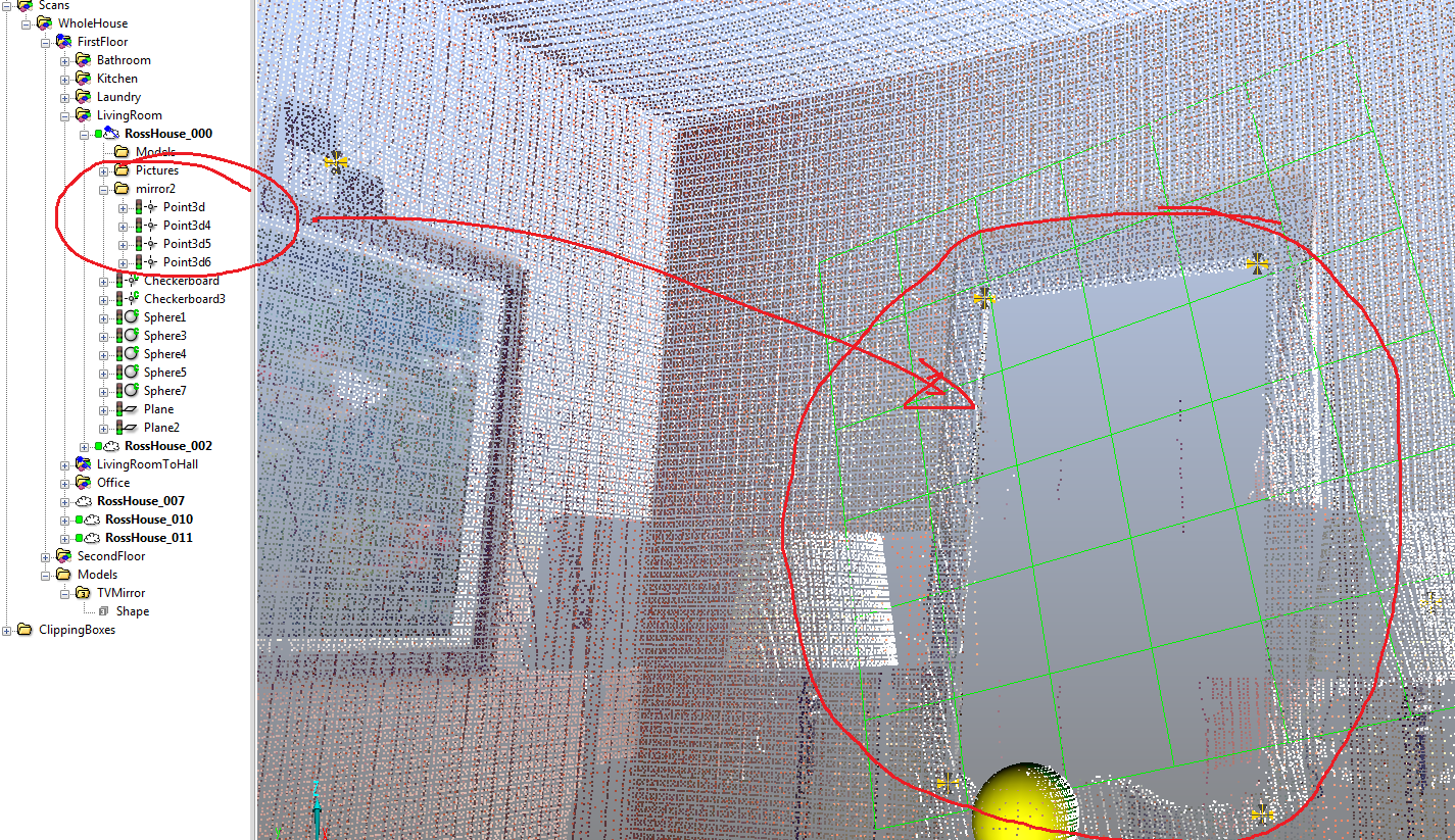
Annotating the mirror
Only planar mirrors are supported, however they might have any number of vertices to their shape. We annotate the mirror straight in the dataset in the LiDAR data's editor. -
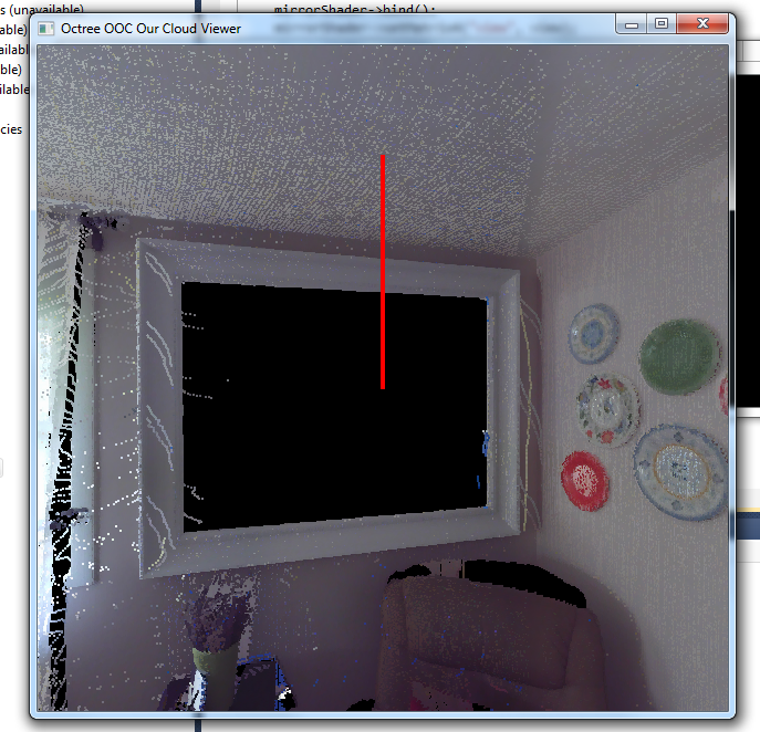
No mirrors
The previous render method. Mirrors are completely missing from the data set and it appears as a black hole in the rendered data. -
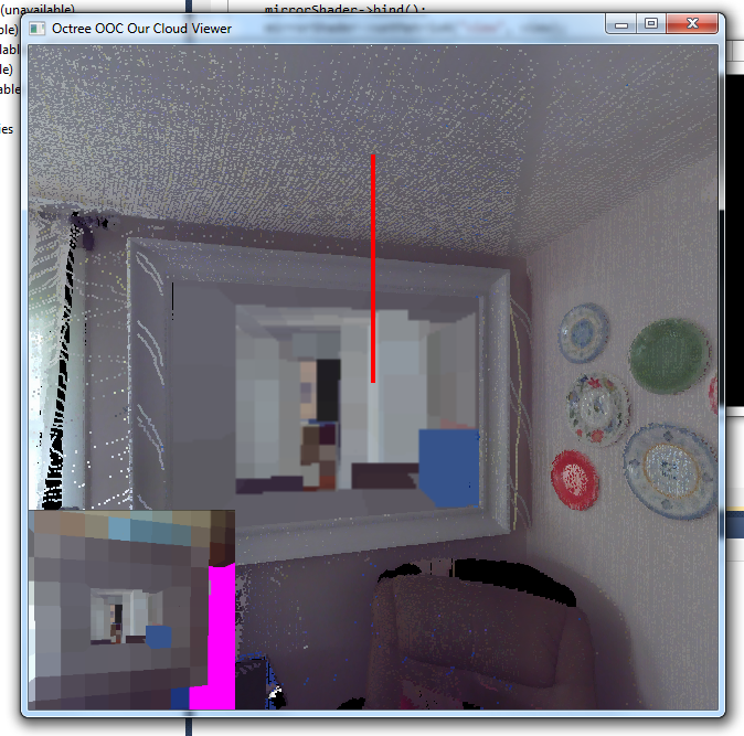
Mirrors
Enabled mirror rendering, including debug output on the lower left. The mirror content is in this image only the voxel data, not the actual point cloud data.