Custom Flightsim Controls Arduino-based TPM stack
Overview
I recently had a lot of fun with the recently released MS Flight Simulator. I even splurged and got myself one of the nice Honeycomb yokes :) The yoke feels great and I was pairing it with my heavy-duty Warthog TQS. However, throttle controls did not feel correct, especially when doing Touch & Go's or Go-arounds in Cessnas. I felt that I could not rely on muscle memory, as the trim, flaps and throttle controls were so different from the actual aircraft. Unfortunately, Cessna-style push-pull controls for simulators are either stupidly expensive or sold out.
This was when I looked again at building my own USB-compatible Joystick using Arduino and a couple of potentiometers. Ideally, the Joystick will show up in the Systems menu as a regular gaming peripheral and will not require any drivers.
The following controls should be simulated:
- Throttle
- Prop/Rpm
- Mixture
- Flaps
- Trimwheel
All of the inputs will be read from potentiometers through analog inputs and will show up as dedicated controller axis.
Hardware
The list of electronic hardware thus runs:
- Teensy 2.0
- 4 slide pots for the power controls and flaps. [These do not have linear tapers as advertised, see below.]
- A rotary pot for the trim wheel
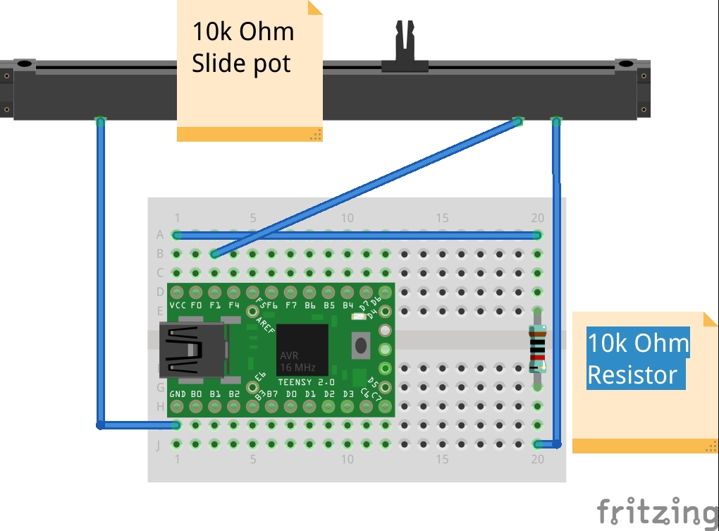
- 10k resistors
- Cables, etc
Initial Experiments
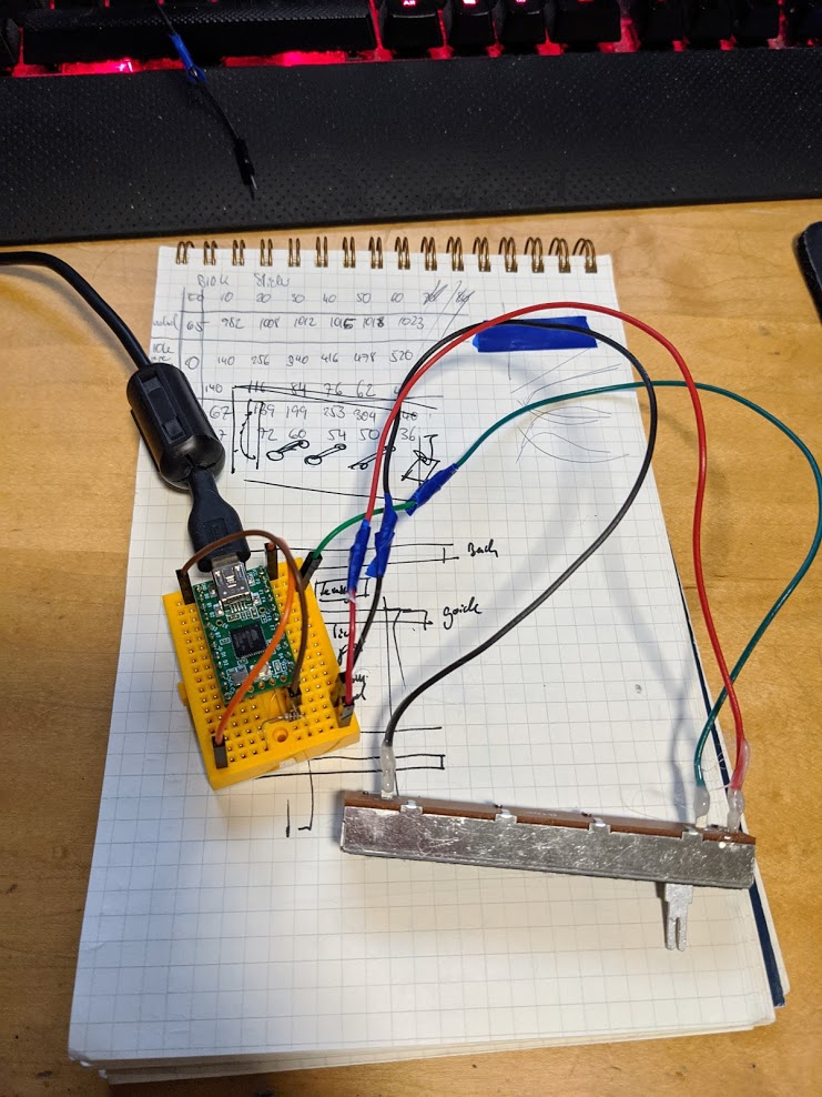
After getting all the hardware, I hooked them up to the Teensy/Arduino and started reading figuring out how to read the values and talk back the PC as a USB device.
Slide potentiometer response curve
The Slide potentiometers I got were advertised as having a linear response curve/taper. Unfortunately, that's not true. They have the same taper description (B10K) as my rotatary pot but give a distinct logarithmic response. I measured the raw analog value Arduino read every 10mm of the handle's position (see table below). The raw input is pretty much unusable, reporting 90% of its resolution in the first 10mm of travel. Adding a 10k resistor in line with the pot dampens the effect so that responds almost linearly, however it costs about half the resolution (0--512 compared to 0--1024). The higher resolution for the rotatary pot is not too bad, as I wanted to use it for the trimwheel anyway.
| Pot/Position | 00 | 10 | 20 | 30 | 40 | 50 | 60 |
|---|---|---|---|---|---|---|---|
| Direct | 65 | 982 | 1008 | 1012 | 1015 | 1018 | 1023 |
| With 10k resistor in line | 0 | 140 | 256 | 340 | 416 | 478 | 520 |
Arduino Code
The Arduino code is very simple and contains no logic at all. It reads the value from the potentiometers through analog input pins and writes the values directly to either Arduino's Serial (for testing) or Teensy's Joystick library.
The code looks something like this:
        void loop()
        {
          int poti = analogRead(A0);

          // Either or -- Teensy does not like USB serial while pretending to be a Joystick?
          Serial.println(poti);
          Joystick.X(poti);

          delay(10);
        }
and is then repeated for each axis: throttle, prop, mixture, trim and flaps:
        void loop()
        {
          // Throttle
          Joystick.X(analogRead(A0));
          // Prop
          Joystick.Y(analogRead(A1));
          // Mixture
          Joystick.Z(analogRead(A2));
          // Flaps
          Joystick.Zrotate(analogRead(A4));
          // Trim
          Joystick.sliderLeft(analogRead(A5));

          delay(10);
        }
The code above sends 5 input events every 10ms. These can be combined into a single USB input event if we use manual triggering:
        void setup()
        {
          Joystick.useManualSend(true);
        }

        void loop()
        {
          // Throttle
          Joystick.X(analogRead(A0));
          // ...
          Joystick.send_now();
          delay(10);
        }
First steps
After selecting Joystick/Mouse/Keyboard in the Teensyduino menu it shows up in Linux' jsgtk manager and can then be calibrated. From there it's only a little step to actually test it in X-Plane 11 :)
Hardware
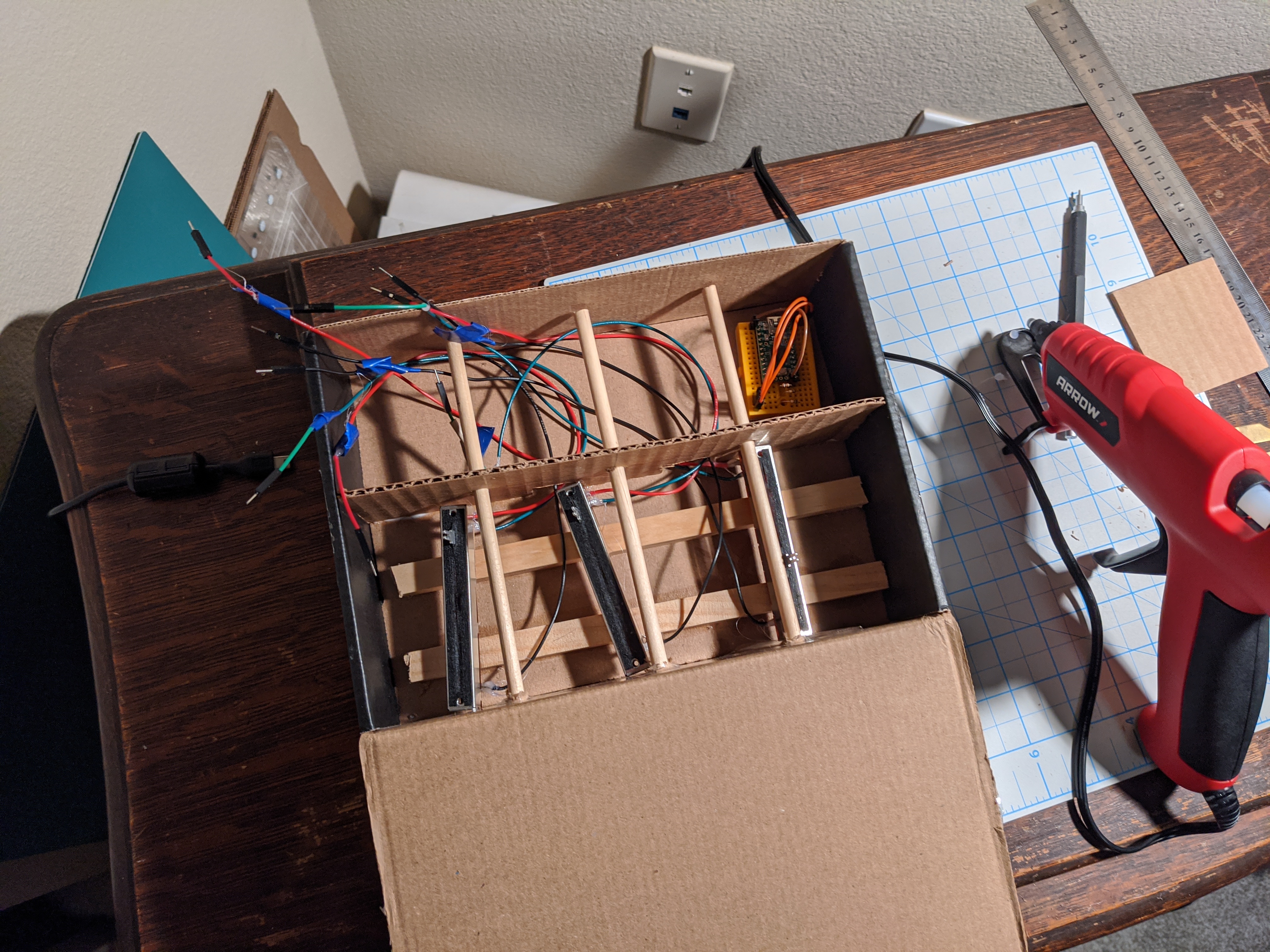
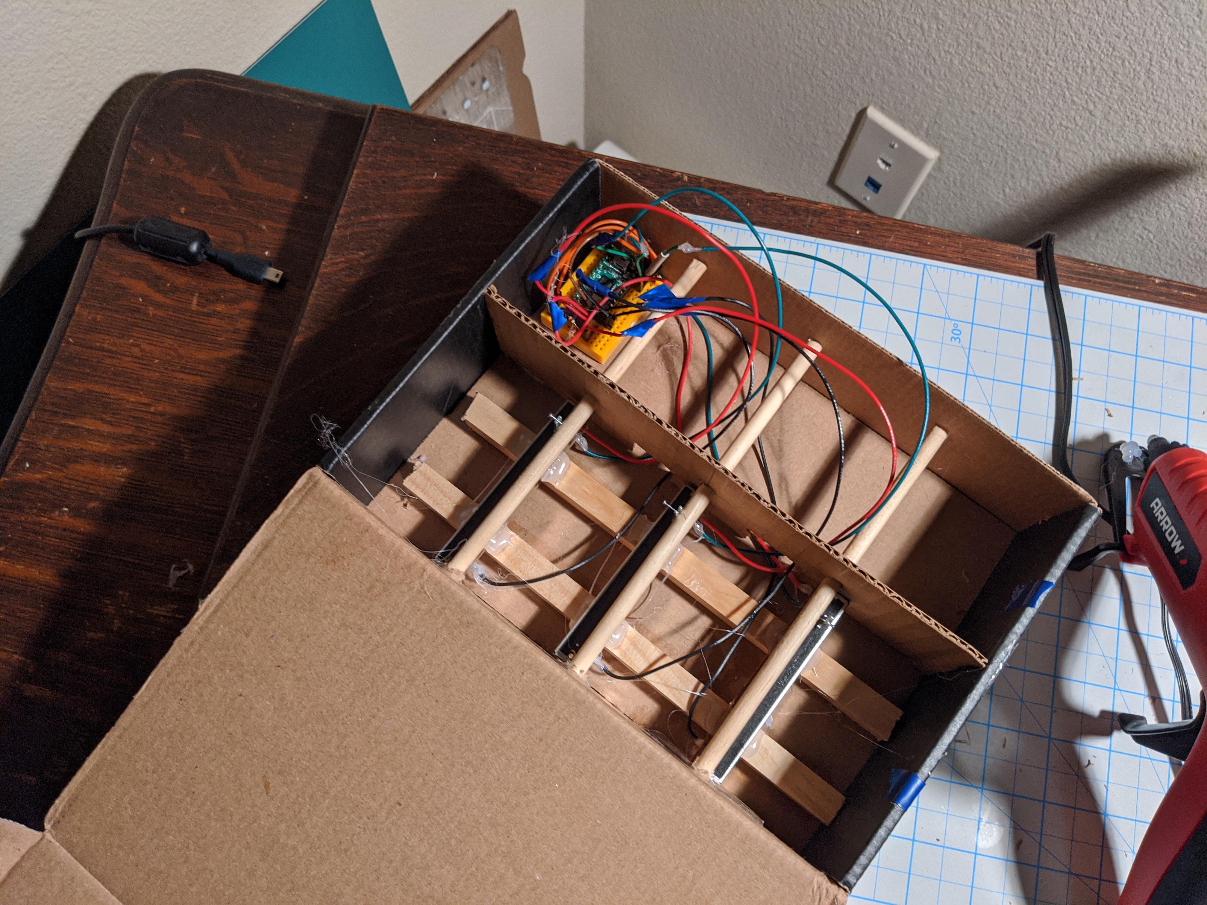
The next big item was the hardware to house the controls in. I went for the cheapest, quickest, prototypy option -- cardboard -- and actually recycled the nice black Adafruit package from my last purchase. Cardboard has the advantage that I could both plan and build at the same time. Making changes, improvements or fixes is super-fast and it does not require any tools which is essential when living in an apartment without a workbench. All materials used are either cardboard or cheap, light-weight hobby wood. However, it's still a prototype and the idea is to test it, fix any outstanding issues and then redo it properly, probably using laser-cut materials.
Build process
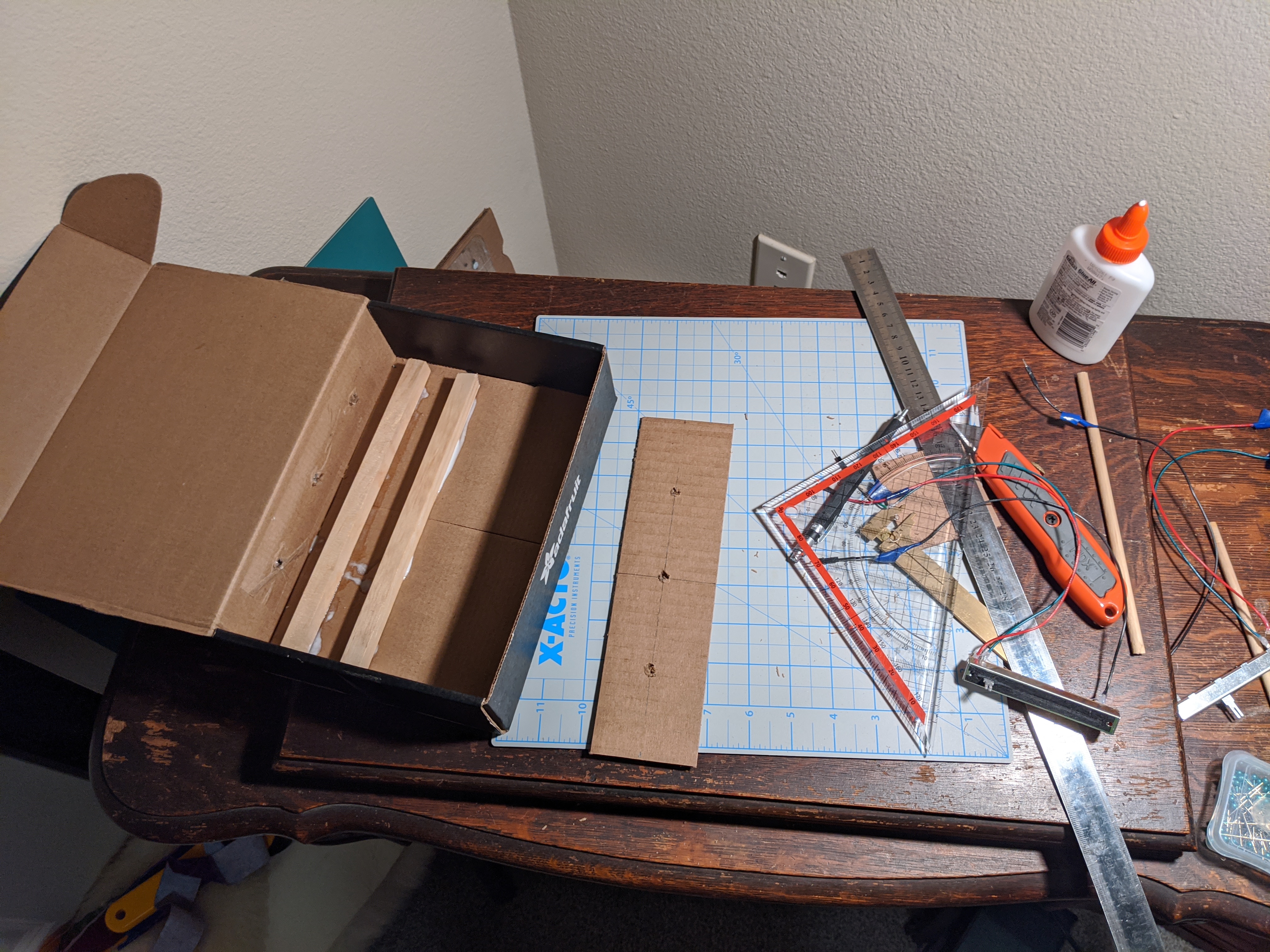
The firewall is constructed and glued in place. I've also added some holes at the bottom for the cables. I've put the wall in place to support the pots in place -- these will be wedged between the box wall and the internal wall. The dowels will extend into the empty space to the right.
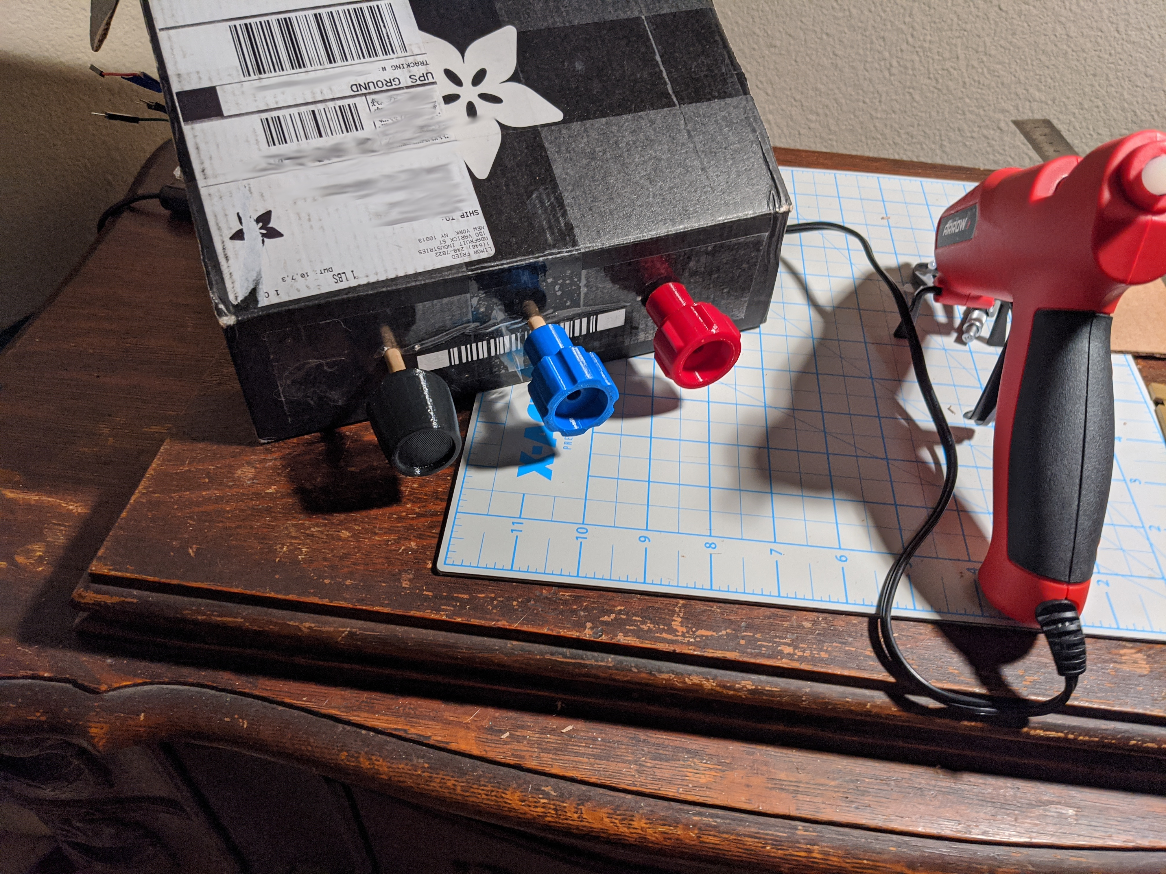
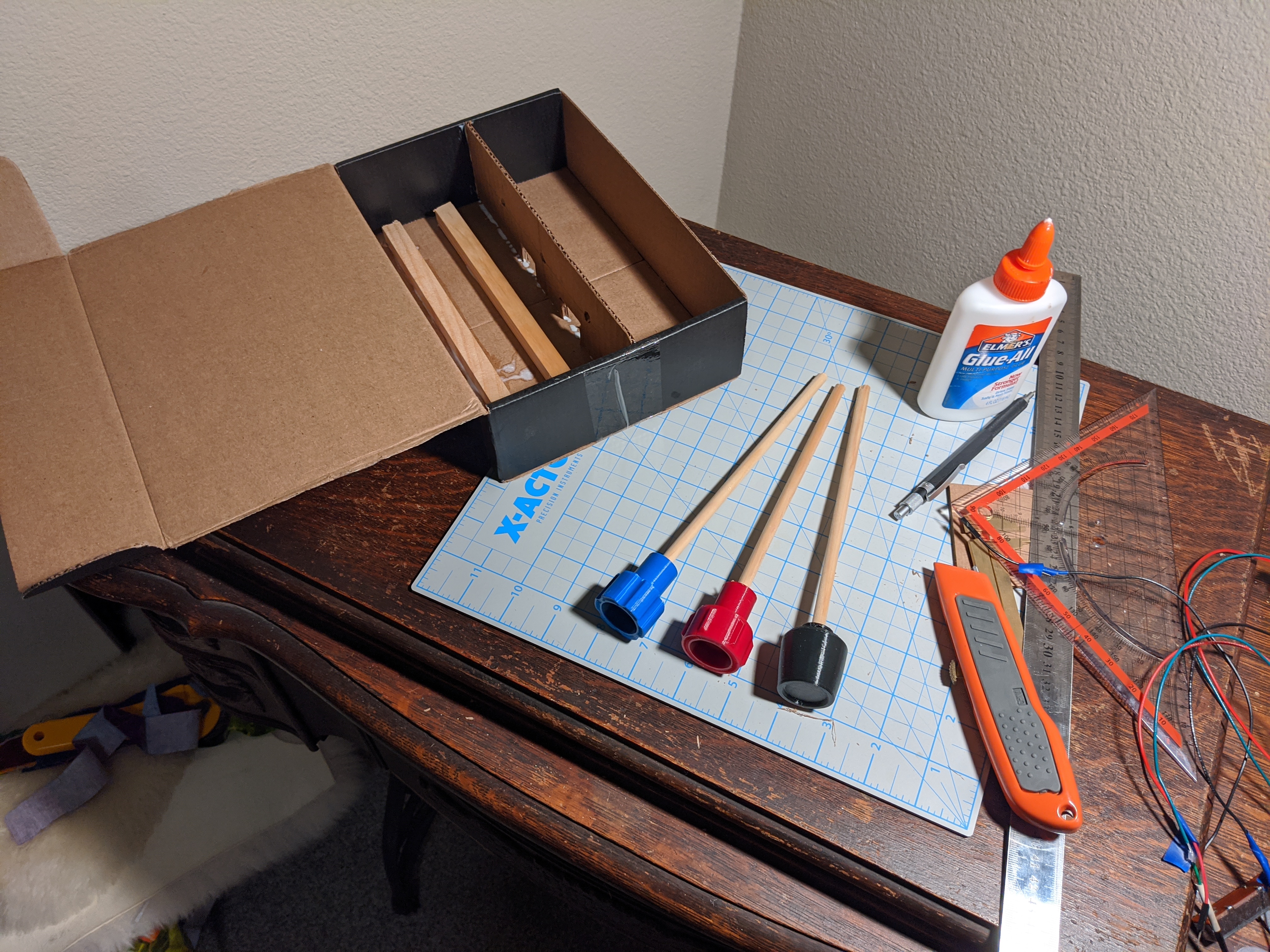
Speaking of, I've ordered 3D prints of Cessna control knobs off of Treatstock; quality was good and they arrived fairly fast. They're friction-fitted onto the wooden dowels with no glue needed (hooray for brute force). These feel great -- exactly what I was after when starting on this projectr.