Software Rasteriser Secondary Text
Features
Pipeline
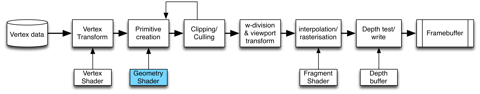
The pipeline is very similar to current graphics pipelines, such as OpenGL. Shader support was a core component from the beginning. Vertex and fragment shaders are implemented and a combined tesselation/geometry shader is planned. To actually implement a shader on the user side, the Vertex or FragmentShader superclass is used to derive the more specialized shader. This also allows to quickly change between shaders during runtime.
Data flow and structs
Geometry is passed to the renderer as a vertex and index lists. A vertex is very bare bone, it consists of a POD structure, containing a position, a normal, colour and texture coordinates:
struct Vertex
{
    vec4        position;
    vec3        normal;
    vec4        colour;
    vec2        texcoord;
};
The index list is just an array (or vector) or unsigned ints. All vertices are transformed by the vertex stage in one go. The vertex shader transforms the input vertices to output vertices:
struct ClipVertex
{
    vec4        clipPosition;
    vec3        worldPosition;
    vec3        worldNormal;
    vec4        colour;
    vec2        texcoord;
};
The ClipVertex requires the shader to calculate the clip and world positions for the vertex and the normal in normal space. The former is used for further rasterisation, the latter is used for lighting calculations in world space.
During primitive assembly, the requested primitives (points, lines or triangles) are assembled, based on the transformed vertices and the indices. Backface culling is implemented at this point for triangles: the triangle’s face normal is calculated via the cross product of it’s edges in normalised device coordinates. If the normal’s z component is negative, the normal is pointing away from the camera and the triangle gets discarded.
Primitive assembly is currently fixed-function only, but should be replaced or supplanted by a geometry shader later on. In current GPUs, the geometry and tessellation shader are different entities, however there is no reason to separate them in a software rasteriser. A complex geometry shader could, for example, be used to implement a REYES-like rendering architecture by tessellating incoming primitives until their projections occupy an area smaller than a single pixel.
The primitives are then culled and clipped against the homogenous cube (-w <= (x,y,z) <= w) before the depth division and the calculation of the final window coordinates. Afterwards the primitives are rasterised while keeping track of a running interpolation variable. Before anything is written to the colour buffer a depth test is performed and only if this succeeds is a shading geometry variable created which is passed into the fragment shader.
Shaders
Similar to OpenGL or DirectX, shaders are located at three places in the pipeline. Currently, all the shaders are stream-oriented, they take one well-defined input struct and transform/compute another output struct.
The Vertex Transform is the vertex shader in current GPU-based architectures. An input vertex is transformed from model-space to clip-space using three distinct matrices: the model, view and projection matrix. The output is a ClipVertex and stored in a second array.
The geometry shader runs during primitive assembly and takes a list of input indices and the transformed vertices to create render primitives in clip space. It is also able to discard primitives and to create new ones, based on the input.
Finally, the fragment shader runs for every fragment that passes the z-test during rasterisation. Its input is a shading geometry struct and its output a single colour.
Rasterisation and Clipping
Line rasterisation is done using the classic Bresenham algorithm. An additional float counter keeps track of the current position on the line and is used to interpolate the position for a shading geometry, which is passed into the fragment shader for evaluation.
Line clipping is performed in projective space, where each line is compared against the planes of the clip cube in (-1,-1,-1) … (1,1,1). This happens in clip space, so no actual frustum or matrix information is needed for clipping. This is great as it keeps the vertex transform to the previous shader stages.
Triangle rasterisation is performed using the method described by ryg in his blog post. After the primitive creation and back face culling test the three points of the triangles are calculated in screen space and a bounding box is created. The rasterisation process is simple but has some interesting twists.
Each pixel in the bounding box is then checked against the three edges of the triangle and determined whether the pixel lies on the outside or the inside. Only if the pixel in question falls inside for all three edges, it is rendered. Note that all point-line distances are calculated in image space and are therefore in pixels; the algorithm even handles screen-space clipping for each triangle during rendering, as the bounding box itself is clipped against the viewport. I have not yet run performance evaluations, but I think it might be slower than a span-based rasteriser for some triangles that take up little space in their bounding boxes (for example, the triangle on the right in the image above). The barycentric coordinates are calculated and passed into the fragment shader for evaluation.
Pictures
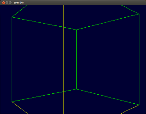
Line clipping
Green: fully inside clipspace cube, therefore visible. Yellow: intersecting clip space cube.

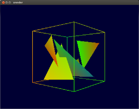
Triangles.
Triangles amd their screenspace bounding boxes. The color indicates the barycentric coordinates.
Z-Buffering
Occlusion is handled using a per-pixel depth test and a depth buffer.
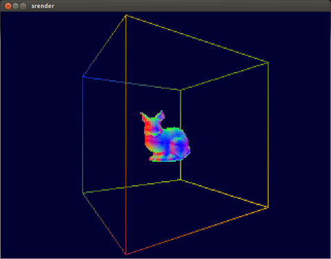
Geometry
A single triangle is not that interesting, however many triangles are combined into a mesh, for example the Stanford Bunny, which is rendered here with a normal visualisation shader.
Parallel Rendering
After triangle rasterisation has been implemented, the next step should be parallelisation of the pipeline. Small-scale parallel code is already in place in SIMD-friendly math structs for vectors and matrices. Parallelisation of the larger rendering context could be done using tile-based rendering. The frustum could be subdivided into according to the screen-space of these tiles. It's probably only necessary to adjust the frustum's clipspace extend (eg not from -1 to 1, but from -1 to -0.5, or similar). However, it would not be efficient to clip each individual triangle against these sub-frusta, so more generalized geometry structs, including bounding volumes should be rendered.
Subdivision Primitives
Supporting subdivision primitives, such as quads would be another interesting side-project. This would follow the basic REYES idea: after culling but before rasterization, the screen-space size of these patches would be checked. If they are bigger than a pre-defined size (let's say one pixel), they will be subdivided into equal parts (dicing). Afterwards, culling/dicing would continue on these children until they are not bigger than the dersired size.
Source Code
Here's an archive with all the files as I found them lying around my harddrive ...